
Concept Notes
1. Introduction to SCR
- SCR = Silicon Controlled Rectifier.
- It is a four-layer, three-junction, three-terminal device (PNPN).
- Terminals:
- Anode (A) → Connected to outer P-layer
- Cathode (K) → Connected to outer N-layer
- Gate (G) → Controls device triggering
SCR behaves like a controlled switch:
- OFF → Blocks current in forward direction (until triggered).
- ON → Conducts heavily when gate signal is applied.
2. Modes of Operation
- Forward Blocking Mode
Anode is positive wrt Cathode, but no gate pulse → Device does not conduct. - Forward Conduction Mode
Apply gate pulse in forward bias → SCR turns ON → Large current flows. - Reverse Blocking Mode
Cathode positive wrt Anode → Reverse leakage current flows (very small).
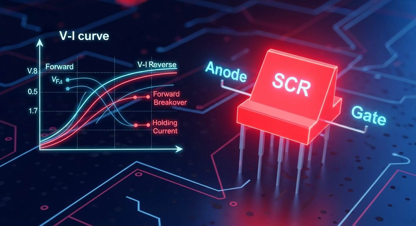
3. V–I Characteristics of SCR
- Forward Blocking Region: Anode positive, no gate signal → current ~ 0.
- Breakover Voltage (V_BO): Beyond this, device turns ON without gate signal.
- Gate Triggering: Applying small current at Gate reduces breakover voltage.
- Forward Conduction Region: SCR conducts heavily with small voltage drop (~1-2V).
- Reverse Blocking Region: High reverse voltage, small leakage current.
- Holding Current (I_H): Minimum current required to keep SCR ON.
- Latching Current (I_L): Minimum current needed immediately after triggering to latch SCR into conduction.
4. Applications of SCR
- Power control (AC regulators, lamp dimmers)
- Motor speed control
- Rectifiers (controlled rectifiers)
- Inverters & UPS
- Industrial automation (PLC-based firing control)
⚙️ Formulas
- Breakover Voltage:

- Latching Current:

- Holding Current:

- Forward Voltage Drop (ON state):

- Gate Power:

🔟 10 MCQs
Q1. SCR is a ___ layer, ___ junction device.
a) 2-layer, 1-junction
b) 3-layer, 2-junction
c) 4-layer, 3-junction
d) 5-layer, 4-junction
Q2. The three terminals of SCR are:
a) Anode, Base, Collector
b) Anode, Cathode, Gate
c) Source, Gate, Drain
d) Emitter, Collector, Base
Q3. SCR remains OFF in forward bias until:
a) Anode is negative
b) Cathode is positive
c) Gate pulse is applied or V_BO is reached
d) None
Q4. The minimum current required to keep SCR ON is called:
a) Latching Current
b) Holding Current
c) Breakover Current
d) Leakage Current
Q5. Which statement is true about Latching and Holding currents?
a) 
b) 
c) 
d) None
Q6. Typical ON-state voltage drop of SCR is:
a) 0.1–0.3V
b) 1–2V
c) 5–10V
d) 20V
Q7. In reverse bias, SCR current is:
a) Very large
b) Zero
c) Small leakage current
d) None
Q8. Which of the following is an application of SCR?
a) Motor speed control
b) Voltage regulation
c) Power amplification
d) Oscillation
Q9. PLC can be used with SCR for:
a) Heat sink design
b) Gate triggering control
c) Manufacturing the device
d) None
Q10. Gate power is given by:
a) 
b) 
c) 
d) 
✅ Answer Key
| Q.No | Answer |
|---|---|
| 1 | c |
| 2 | b |
| 3 | c |
| 4 | b |
| 5 | b |
| 6 | b |
| 7 | c |
| 8 | a |
| 9 | b |
| 10 | c |
🧠 Explanations
- Q1: SCR has 4 layers (PNPN), 3 junctions → (c).
- Q2: Terminals are Anode, Cathode, Gate → (b).
- Q3: Turns ON only when gate pulse applied or V_BO exceeded → (c).
- Q4: Holding current keeps device ON → (b).
- Q5: Latching current > Holding current → (b).
- Q6: On-state voltage drop ~1–2V → (b).
- Q7: In reverse bias, small leakage flows → (c).
- Q8: SCR is widely used in motor speed control → (a).
- Q9: PLC controls firing angle & gate triggering → (b).
- Q10: Gate power = → (c).
🎯 Motivation / Why Practice Matters
Power Electronics is a core strength area in ECET 2026. Questions on SCRs and their V–I characteristics are guaranteed every year. Understanding concepts like latching current, holding current, and triggering methods is vital for solving rectifier & chopper problems. Practicing these basics will make later chapters (inverters, converters, drives) much easier.
📲 CTA
👉 Join our dedicated ECET 2026 WhatsApp Group for daily practice, notes & quizzes:
🔗 Join Now