Concept Notes
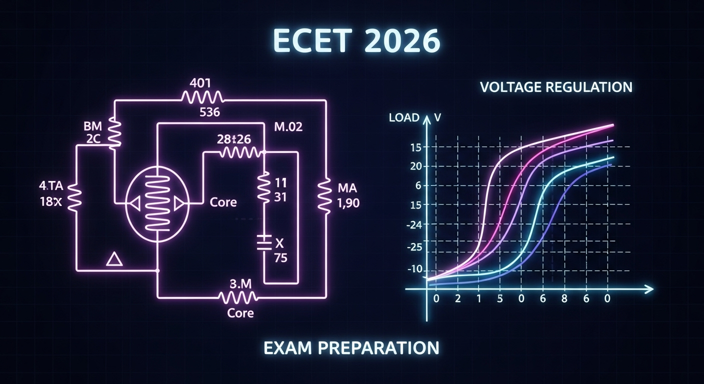
1. Equivalent Circuit of a Transformer
The real transformer has losses and leakage, so we represent it with an equivalent circuit that closely matches practical performance.
- Primary Side Parameters:
 = Primary winding resistance
 = Primary leakage reactance
- Secondary Side Parameters:
 = Secondary winding resistance
 = Secondary leakage reactance
- Magnetizing Branch (Core losses):
 = Core-loss resistance (hysteresis + eddy current losses)
 = Magnetizing reactance (accounts for magnetizing current)
👉 To simplify, secondary parameters are referred to primary side (or vice versa) using turns ratio ![]() .
.
- Referred secondary resistance:

- Referred secondary reactance:

Final Equivalent Circuit:
Series part: ![]()
Shunt branch: ![]()
2. Voltage Regulation of a Transformer
Voltage regulation is the change in secondary voltage from no-load to full-load, expressed as a percentage of full-load voltage.
Formula:
![]()
In terms of equivalent circuit parameters:
![]()


 = Power factor (lagging or leading load)
- Lagging load:

- Leading load:

👉 Good transformer design: Voltage regulation should be low (near 0%), ideally negative under leading PF.
Example:
A 100 kVA transformer has ![]() , load PF = 0.8 lagging, current = 500 A.
, load PF = 0.8 lagging, current = 500 A.
![]()
![]()
(too high just for illustration; in reality <10%).
⚙️ Formulas
- Turns ratio:

- Referred resistance:

- Referred reactance:

- Equivalent resistance:

- Equivalent reactance:

- Voltage regulation:
![]()
🔟 10 MCQs
Q1. The equivalent circuit of a transformer is used to:
a) Reduce losses
b) Represent practical performance
c) Increase efficiency
d) None
Q2. The shunt branch in transformer equivalent circuit represents:
a) Winding resistance
b) Leakage reactance
c) Core losses & magnetizing current
d) Load
Q3. If turns ratio ![]() and
and ![]() , then referred resistance
, then referred resistance ![]() = ?
= ?
a) 0.4 Ω
b) 2 Ω
c) 10 Ω
d) 25 Ω
Q4. The series part of equivalent circuit represents:
a) Core losses
b) Leakage & winding drops
c) Magnetizing current
d) Open-circuit test
Q5. Voltage regulation of an ideal transformer is:
a) Zero
b) Unity
c) Infinite
d) Negative
Q6. A transformer has ![]() lagging. Find %VR.
lagging. Find %VR.
a) 1.5%
b) 2%
c) 3%
d) 5%
Q7. Which load condition can give negative voltage regulation?
a) Unity PF
b) Lagging PF
c) Leading PF
d) No-load
Q8. If ![]() , find
, find ![]() .
.
a) 1Ω, 2Ω
b) 2Ω, 4Ω
c) 3Ω, 2Ω
d) 2Ω, 1Ω
Q9. A transformer with better design should have:
a) High leakage reactance
b) Low regulation
c) High copper loss
d) None
Q10. Thevenin’s equivalent of transformer secondary is useful in calculating:
a) Efficiency
b) Regulation
c) Short circuit current
d) All
✅ Answer Key
| Q.No | Answer |
|---|---|
| 1 | b |
| 2 | c |
| 3 | d |
| 4 | b |
| 5 | a |
| 6 | c |
| 7 | c |
| 8 | b |
| 9 | b |
| 10 | d |
🧠 Explanations
- Q1: Equivalent circuit models actual transformer → (b).
- Q2:
 represent core loss & magnetizing current → (c).
 - Q3:
![Rendered by QuickLaTeX.com R_2' = a^2 R_2 = 25 \times 0.4 = 10Ω → (d).**</li> <li data-start="5131" data-end="5199"> <strong data-start="5133" data-end="5140">Q4:</strong> Series resistance & reactance = winding + leakage → (b). </li> <li data-start="5200" data-end="5258"> <strong data-start="5202" data-end="5209">Q5:</strong> Ideal transformer = no drops, so VR = 0 → (a). </li> <li data-start="5259" data-end="5411"> <strong data-start="5261" data-end="5268">Q6:</strong> [latex] VR = \frac{10(0.5 \cdot 0.8 + 2 \cdot 0.6)}{200} \times 100 = \frac{10(0.4+1.2)}{200} \times 100 = 1.6 \times 5 = 3%](https://learnnewthings.fun/wp-content/ql-cache/quicklatex.com-d56c0ce92300866da0b998423adaee30_l3.png)
→ (c).
Q7: Leading PF can make VR negative → (c).
Q8: ![]() → (b).
→ (b).
Q9: Good transformer = low VR → (b).
Q10: Equivalent circuit helps find all parameters → (d).
🎯 Motivation / Why Practice Matters
Transformers are the backbone of power systems. ECET 2026 will definitely test equivalent circuits and regulation because they connect theory to practical performance (like voltage drop in distribution). Practicing these problems ensures you can handle numerical + conceptual mix questions quickly.
📲 CTA
👉 For daily ECET 2026 prep (notes + quizzes), join our WhatsApp group:
🔗 Join Now


